 |
Software Development
February 2004
Despite its enhanced focus on architecture-oriented diagrams, gaping holes in UI development and data modeling remain, making me wonder: Who needs the OMG?
By Scott W. Ambler
At last ... the OMG’s long-awaited release of UML 2.0! Why has this version lurked on the horizon for so long? Three simple words: Model Driven Architecture (MDA). Most of the work put into UML aimed to increase its precision and consistency, so vendors could develop complex modeling tools that presumably will decrease our reliance on programmers. Having seen integrated computer-assisted software engineering (I-CASE) tools crash and burn in the 1980s, and considering the shallow pool of expert modelers, I hold little hope for MDA. Unfortunately, these are the cards that the IT industry has dealt itself, so we’ll have to live with this version of UML for awhile. Here’s what’s new.
Something for Your Stakeholders
Use case diagrams haven’t changed. Activity diagrams, however, have been completely overhauled. The OMG seems to increasingly recognize that activity diagrams should be used for business process modeling instead of object modeling, so they’ve begun inching toward a combination of traditional data flow diagrams (DFDs) and flow charts. They’re no longer specializations of state machine diagrams, and thus are more flexible. New notation and semantics have been added to model the transformation of objects between activities as well as for event signaling. Unfortunately, they still reflect their object heritage in the fact that objects passed between activities are depicted as object boxes (consistent with other UML diagrams) on the transition lines. Personally, I prefer the much more concise notation used on DFDs—a simple label on the line. Activity diagrams clearly still need to evolve, but they’re definitely moving in the right direction.
Architecture, Anyone?
UML 2.0 boasts a major improvement in its greater focus on architecture-oriented diagrams: component diagrams, deployment diagrams and package diagrams. Component diagrams have evolved, but deployment diagrams haven’t changed and should still be used to interrelate the software, hardware and middleware components. Package diagrams have now been officially added and should still be used for high-level overview diagrams or to depict your source code’s package structure (for example, Java code is organized into packages).
In the past, component diagrams were promoted as detailed design diagrams, and the UML User Guide (Addison-Wesley, 1999) absurdly advised that we use them for data or user interface modeling, reflecting the “everything is a component” mindset of the time. Other methodologists—including me in Process Patterns (Cambridge University Press, 1999), and Peter Herzum and Oliver Sims in Business Component Factory (Wiley, 2000)—suggest using component diagrams for application and even enterprise architecture. The OMG seems to have adopted this philosophy.
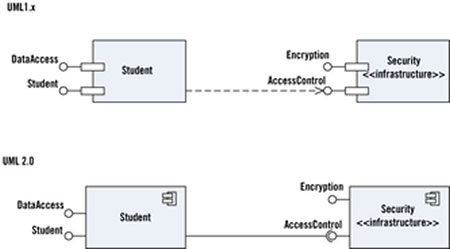
 [click for larger image] Component Diagram Evolution In UML 2.0, components are now simple boxes with a component stereotype, either the “bandaged box” visual stereotype or the <<component>> textual stereotype. |
<<component>> textual stereotype.
The second notation difference concerns interfaces. A socket notation has been added to indicate a required interface: In “Component Diagram Evolution,” the Student component requires the Access Control interface, which is provided by the Security component. The combination of the required interface notation and the traditional lollipop notation is often referred to as ball-and-socket notation. This notation is also used on UML deployment and class diagrams.
Detailed Design Diagrams
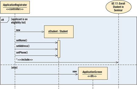
The good news? Class diagrams, the mainstay of most object system designs, are little changed—a few new stereotypes and the ball-and-socket interface notation are about it. Sequence diagramming notation is also basically the same, although the addition of interaction frames in UML 2.0 makes it a little more robust. An interface frame is depicted as a rectangle with an operator box in the top left corner; the “Sequence Diagram” uses an interaction frame to model an if statement. Interaction frames have one or more sections, separated by dashed lines, and are used to model if/switch logic, loops and parallel logic. The sequence diagram also depicts the traditional way of modeling a loop using an iteration marker, an asterisk, to indicate that the use case logic is potentially invoked several times. This notation for looping is still valid in UML 2.0.
 [click for larger image] Sequence Diagram This diagram uses an interaction frame to model an if statement. It also depicts the traditional way of modeling a loop using an iteration marker, an asterisk, to indicate that the use-case logic is potentially invoked several times. |
Timing diagrams, for exploring the changes in state over time of an object or component, have been added. Although business application developers will rarely need them, I suspect that the real-time community may find them very useful.
What Were They Thinking?
I find little use for two new diagrams in UML 2.0. The first is the composite structure diagram, which is used to show the objects involved in a collaboration. I’ve heard that this is good for describing design patterns, but frankly, I think that a combination of class diagrams and sequence diagrams is more effective: They show greater detail, and developers are already familiar with them. The second questionable addition is the interaction overview diagram, which depicts a collection of interaction frames with flow between. It’s too complex to sketch effectively on a whiteboard, and although a CASE tool vendor could do something interesting with it, gut feel tells me that this will be a low priority. I suspect that these two diagrams will receive scant attention in coming years.
The OMG Just Doesn’t Get It
Why is the release of UML 2.0 a non-event? Because it doesn’t address any of UML 1.x’s gaping holes. Every single system that I’ve ever built implements business rules and a user interface, and uses a database to persist objects—yet these three issues still haven’t been addressed. Yes, a business rules working group exists within the OMG, so I hope we’ll see something in UML 2.1. However, UML still doesn’t address user interface development, a serious problem when you consider that the user interface is the system to most users. Several methodologists—including Craig Larman, Jim Connalen, Geri Winters and myself—have suggested approaches to user interface flow modeling (storyboarding) using UML, but no official effort to develop a common profile exists.
UML’s lack of a data modeling profile is of particular concern to me, and several unofficial efforts are underway. IBM Rational has published its own data modeling profile (but unfortunately it’s constrained by their toolset). Oracle includes UML data modeling in JDeveloper 10i, but at press time they hadn’t published a publicly available profile for that work. I maintain a profile, which is effectively open source—anyone, OMG member or not, may contribute. Several tool vendors are looking at it, and some are contributing, so it leads me to question whether the IT industry even needs the OMG to develop UML anymore—if we can develop software in an open-source manner, why can’t we also create a standard modeling language? Needless to say, I’d like to see a similar effort for user interface modeling, or, for that matter, other forms of modeling, to help prove my point.
UML and agility are orthogonal concepts—you can be agile using UML or non-agile; it’s up to you. My advice is to keep your modeling efforts simple, inclusive, cooperative and focused on value. Agile models are just barely good enough, and I’ve found that UML models can be just as agile as non-UML models. The vast majority of models are sketches done on whiteboards that are quickly discarded once they’re no longer needed, and that’s perfectly fine. Modeling, including but not limited to UML, is an important part of any agilist’s toolkit.
Editor’s Note: The two diagrams are modified from The Object Primer, 3rd Edition: Agile Model Driven Development with UML 2, to be published in March 2004 by Cambridge University Press.