At this point in its evolution, the UML is recognized as a modeling language, not as a methodology or method. The difference is that a modeling language is more of a vocabulary or notation (in the case of UML, a mostly graphical notation) for expressing underlying object-oriented analysis and design ideas. A method or process consists of recommendations or advice on how to perform object-oriented analysis and design.
This article explains the UML notation, describes each UML modeling diagram, provides an example where appropriate, and indicates when the diagram can be used. I'm not going to go into enough detail to teach you how to actually model with UML; instead, at the end of the article, I'll outline a simple and useful process that uses UML.
The UML diagrams I'll cover will include the following:
A use case scenario is a description, typically written in structured English or point form, of a potential business situation that an application may or may not be able to handle. A use case describes a way in which a real-world actor-a person, organization, or external system-interacts with your organization. For example, the following would be considered use cases for a university information system:
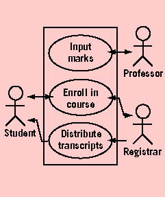 |
| Figure 1. An Example of a Use Case Diagram |
The combination of use cases and their corresponding use case diagram is referred to as a use case model. Use case models are often accompanied by a glossary describing the terminology used within them. The glossary and use case model are important inputs for the development of class diagrams.
Class Diagrams
Class diagrams, formerly called object models, show the classes of the system and their interrelationships (including inheritance, aggregation, and associations). Figure 2 shows an example of a class diagram, using the UML notation that models my Contact-Point analysis pattern. Class diagrams are the mainstay of object-oriented modeling and are used to show both what the system can do (analysis) and how the diagram will be built (design).
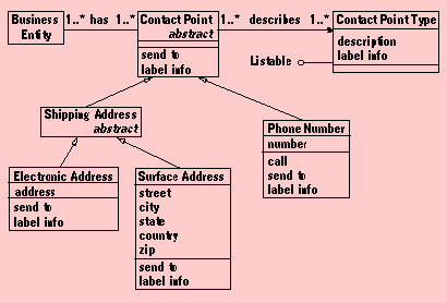 |
| Figure 2. A Class Diagram Representing the Contact-Point Analysis Pattern |
Classes are documented with a description of what they do, methods are documented with a description of their logic, and attributes are documented by a description of what they contain, their type, and an indication of a range of values (if applicable). Statechart diagrams, covered later, are used to describe complex classes. Relationships between classes are documented with a description of their purpose and an indication of their cardinality (how many objects are involved in the relationship) and their optionality (whether or not an object must be involved in the relationship).
Sequence Diagrams
A sequence diagram, formerly called an object-interaction or event-trace diagram, is often used to rigorously define the logic for a use case scenario. Because sequence diagrams look at a use case from a different point of view from which it was originally developed, it is common to use sequence diagrams to validate use cases. Figure 3 shows an example of a sequence diagram. Depending on your modeling style, it's also common to use sequence diagrams during design to understand the logic of your application. This is usually done by a group of developers, often the programmers responsible for implementing the scenario, led by the designer or architect for the project.
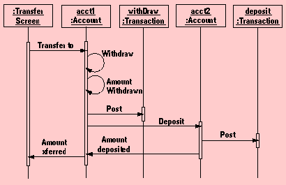 |
| Figure 3. A Sequence Diagram for Transferring Funds from One Account to Another |
Sequence diagrams are a great way to review your work, as they force you to walk through the logic to fulfill a use case scenario. They also document your design, at least from the use case point of view. By looking at what messages are being sent to an object, component, or use case, and by looking at roughly how long it takes to run the invoked method, sequence diagrams give an understanding of potential bottlenecks, letting you rework your design to avoid them. When documenting a sequence diagram, it's important to maintain traceability to the appropriate methods in your class diagram(s). The methods should already have their internal logic described as well as their return values (if they don't, you should document them immediately).
Component Diagrams
Component diagrams show the software components that make up a reusable piece of software, their interfaces, and their interrelationships. For the sake of this article, I take the component/package approach to architectural reuse. This approach is described in Ivar Jacobson's latest book Software Reuse (Addison Wesley, 1997). From this vantage, a component may be any large-grain item-such as a common subsystem, an executable binary file, a commercial off-the-shelf system, an object-oriented application, or a wrapped legacy application-that is used in the day-to-day operations of your business. In many ways, a component diagram is simply a class diagram at a larger, albeit less-detailed, scale.
Figure 4 shows an example of a component diagram that models the architectural business view of a telecommunications company. The boxes represent components, in this case either applications or internal subsystems, and the dotted lines represent dependencies between components. One of the main goals of architectural modeling is to partition a system into cohesive components that have stable interfaces, creating a core that need not change in response to subsystem-level changes. Component diagrams are ideal for this purpose.
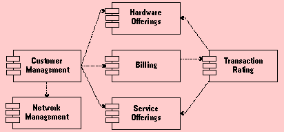 |
| Figure 4. A Component Diagram for the Architectural Business View of a Telecommunications Company |
This approach to component diagrams is contrary to what the UML document currently suggests. The current use for component diagrams proposed by the UML document is that it is an implementation diagram that shows the granular components, perhaps ActiveX components or Java Beans, used during implementation. Although these kinds of components are important, this is a low-level approach to reuse. Bigger payback is achieved from taking an architectural approach to development. The manner in which I suggest using component diagrams supports this approach. Besides, you still have deployment diagrams to document your implementation decisions.
Deployment Diagrams
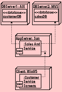 |
| Figure 5. A Deployment Diagram for a Three-Tier Client/Server Application |
For each component of a deployment diagram, you'll want to document the applicable technical issues such as the required transaction volume, the expected network traffic, and the required response time. Further, each component will be documented by a set of appropriate models. For example, the databases will be described with data models, the application server will be described with a component diagram or class diagram, and the customer service screens will at least be documented by an interface-flow diagram and a prototype.
Statechart Diagrams
Objects have both behavior and state; in other words, they do things and they know things. Some objects do and know more things, or at least more complicated things, than other objects. Some objects are incredibly complex, so statechart diagrams are drawn to describe how they work, as shown in Figure 6.
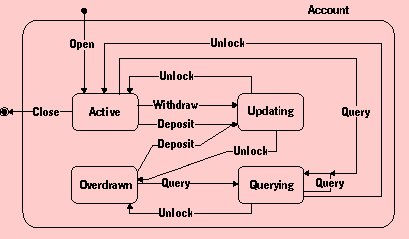 |
| Figure 6. A Statechart Diagram for a Bank Account |
Collaboration Diagrams
Unlike some notations that show both state and behavior on class diagrams, the UML separates behavior into collaboration diagrams. The basic difference between the two approaches is that UML class diagrams don't include messages because messages tend to clutter your class diagrams and make them difficult to read. Because UML class diagrams don't show the message flow between classes, a separate diagram, the collaboration diagram, was created. Collaboration diagrams show the message flow between objects in an object-oriented application and imply the basic associations between objects.
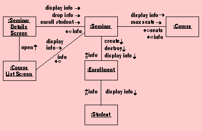 |
| Figure 7. A Collaboration Diagram for a Simple University Application |
Collaboration diagrams are usually drawn in parallel with class diagrams, especially when sequence diagrams haven't been developed for your application. You can use collaboration diagrams to get the big picture of the system, incorporating the message flow of many use case scenarios. Although you can indicate the order of message flow on a collaboration diagram by numbering the messages, this typically isn't done because sequence diagrams are much better at showing message ordering.
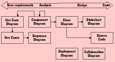
How the UML Diagrams Fit Together
In Figure 8, the boxes represent the main diagrams of the UML, and the arrows show the relationships between them. The arrowheads indicate an "input into" relationship. For example, a use case diagram is an input for a class diagram. Figure 8 provides insight into one of the fundamentals of object-oriented modeling. The relationships between the various models of the UML are reflections of the iterative nature of object-oriented modeling.
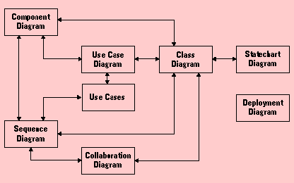 |
| Figure 8. UML Modeling Techniques from an Iterative Point of View |
 |
| Figure 9. UML Modeling Techniques from a Serial Point of View |
At the beginning of large object-oriented projects, you typically start with requirements-gathering techniques such as use cases, then move forward into analysis and design techniques such as class diagrams, and finally progress to spending the majority of your efforts coding. Although you are iterating through all of these techniques, and you may very well write some code at the beginning of your project, the fact remains that you generally need to identify requirements first, then analyze them, then design your software, then code it. In other words, object-oriented development is serial in the large and iterative in the small. Let's spend some time discussing a simplified modeling process using the UML diagrams that we've already discussed.
Class-Driven Application Modeling
Figure 10 shows a modeling process that I call "class-driven" because requirements are captured via class responsibility collaborator (CRC) modeling. CRC modeling is a technique in which a group of domain experts, led by a facilitator, defines the requirements for an application on standard index cards organized in three sections: the name of the class, its responsibilities (what the class knows and does), and the other classes with which the class collaborates to fulfill its responsibilities.
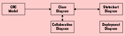 |
| Figure 10. A Class-Driven Modeling Process |
An interesting difference between a class-driven modeling process and one that revolves around use cases (see Figure 1) involves the use of collaboration diagrams and not sequence diagrams. Use case and class diagrams show similar information-the dynamic behavior of your software-although in a slightly different manner. Sequence diagrams are excellent for documenting the logic of a single use case, whereas collaboration diagrams are more appropriate for showing the logic of what may be several use cases. When you take an approach in which use cases are used to define requirements, you may be tempted to use sequence diagrams. With a class-driven approach, you're tempted to use collaboration diagrams because they're closer in a notational sense to class diagrams than sequence diagrams are.
I prefer to use collaboration diagrams when I need to show asynchronous messaging between objects, and I prefer sequence diagrams for synchronous logic. Yes, the UML provides mechanisms for showing asynchronous messaging on sequence diagrams, and synchronous messaging on collaboration diagrams, but frankly the mechanisms are clunky at best. Each UML diagram has its strengths and weaknesses, and this is a perfect example of when you want to use one diagram over another.
The application and system modeling process shown in Figure 10 is one of many that your organization can employ. My general rule of thumb is to develop a diagram if it helps me understand what I'm building, but if it isn't going to help, I don't develop it.